
The WxPic's Tab Pages
The tab pages gather the data managed by WxPic and the controls that allows to set up WxPic. The items are distributed in the following pages:
- Code
- Displays/Edits the program code buffer(s).
- Data
- Displays/Edits the data buffer if the selected component has one.
- Device Config
- Allows to select the device and Display/Edit the configuration in symbolic way.
- Config Memory
- Displays/Edits the configuration buffer in hexadecimal or binary representation (including the the configuration words that are managed by the Config PIC page).
- Options
- Configures the WxPic behaviour.
- Interface
- Allows to select the programmer interface and provides debugging tools for this interface.
- Messages
- Displays the error and debug messages.
The Code Page
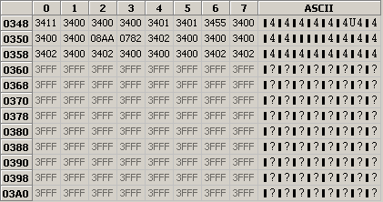
This page displays the code buffer content modified by the user editing if any. Editing is possible when enabled through the Enable HEX editor menu (this is the default). To be effective the changes must be applied.
The left column indicates the address at the beginning of the row. The top row indicates the address offset of the column from the beginning of the row. The cells in the center display the hexadecimal representation of the code memory word values. The right column displays the US ASCII representation of the word bytes. The word bytes are ordered Less Significant first. The bytes not in the range 20 to 7F (hexa) are displayed as a rectangle.
The word values can be edited through either the Hexadecimal representation or the ASCII representation. When editing the ASCII representation, the input is rejected if one of the following error is detected:
- The number of characters does not match exactly the number of Bytes in the words of the row.
- A character not in the range 20-7F (hexa) has been entered and this is not a rectangle.
- A rectangle is provided for a byte that was represented by another character before the edition.
- A given ASCII value does not fit in the number of bits of the word.
A rectangle in the input keeps unchanged the byte value that was present before editing.
The colour of hexadecimal cells indicates the word state that can be:
- Used word
- Contrasted colour that can be adjusted in the Options page.
- Unused word (its value should be equal to the erased word value)
- Dimmed colour.
- Erroneous word (there is a difference between the buffer and the device memory)
- Rouge
- Special word (calibration)
- Violet
The Data Page

This page displays the data buffer content modified by the user editing if any. Editing is possible when enabled through the Enable HEX editor menu. To be effective the changes must be applied.
The left column indicates the address at the beginning of the row. The top row indicates the address offset of the column from the beginning of the row. The other cells contains the hexadecimal or ASCII representation of the data. Editing is performed in the same way as in the Code Page.
The Device Configuration Page

This page allows to select the device to program in a dropdown list. It is possible to declare new devices by editing the Device.ini file.
Depending on the selected device, the code and data memory sizes are displayed in the device properties frame. The disabled checkbox indicates, when checked, that the device memory is flash memory.
The hexadecimal value of the device configuration words are displayed (one or two words depending on the selected device).
The meaning of this configuration is provided by the table below. Each line represents a device configuration parameter. The columns indicate:
- The parameter name,
- The address of the configuration word that contains this parameter,
- The hexadecimal mask that corresponds to the bits of the configuration word that code the values of this parameter,
- The meaning of the current values of these bits.
The list of parameters depends on the selected device.
Editing of the configuration words either from the hexadecimal field or from the Setting column of the table, is possible when enabled through the Enable HEX editor menu. To be effective the changes must be applied. The edition of the setting in the table is modifiable by selecting a new value in a dropdown list that contains the possible values of the parameter. This list is displayed upon a double clic on the cell to modify (when editing is enabled).
The saved before erase information is the values of calibration data that are factory programmed but that are erased by the erase operation. WxPic saves this information to be able to reprogram them and avoid loosing the calibration values. In addition this information is displayed in this page.
TopThe Config Memory
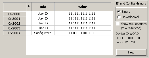
This page displays in a table the value of configuration buffer words. It contains among others the configuration words managed by the Device Config Page. Each row of the table displays a device configuration buffer word. The columns indicates respectively:
- The word address,
- The reserved status of the word when a star is displayed,
- The aim of this word,
- The current value of this word in a hexadecimal or binary representation.
In the right panel, the radio buttons allow to select between the hexadecimal and binary representation of the config words.
The checkbox allows to display, when checked, all the words of the configuration buffer even those that are reserved. The reserved words are not writable and often not used. When reserved words are displayed they are marked with a star in the left column.
The device ID provides the value of the words that indicates device model (for those that supports this feature). The translation of this value in device name is provided. It should correspond to the selected device.
Editing is possible when enabled through the Enable HEX editor menu. The config word values may be edited in Binary or in Hexa decimal whatever the selected display format. The syntax for binary data is only 0 or 1, separated by optional spaces. Number of bits must match exactly. When not matching binary data, the syntax is interpreted as hexadecimal data. Hexadecimal format may start with "0x" or "h", or terminate with "h" (upper case allowed too). The other characters must all be hexadecimal. No space are allowed in the value but it may exist leading or trailing spaces. Once the entry validated it is redisplayed formatted as requested by the format selection. To be effective the changes must be applied.
Top
Configuration memory and ID Locations
Most of the configuration memory addresses store identification information (ID). These locations most often contain four or seven bits per location. For example in "14-bit" devices these locations are mapped to addresses 0x2000 to 0x2003. In contrast to the code memory, the ID locations can be read unscrambled even if the PIC is protected.
In MPASM (the assembler from microchip), there is the __idlocs command (with two underscores) to set these bits, but only the lowest 4 bits in every location. The __idlocs command bundles 4 * 4 bits in a single 32-bit value, presumably because older PICs only had 4 usable bits per ID location. But the 12F675 for example has seven bits per location !
With WxPic, you can read / modify / write the ID locations (all bits). If ID location data are contained in a HEX file, they will be loaded and displayed also. WxPic does not display the data in MPASM's 4*4-bit-format, it uses a table where all bits are displayed in binary form. You can edit the contents of the grid table. After doing so, click the Apply edits button under the table. Clicking this button copies the table contents into an internal buffer, but does not program them into the PIC immediately - the ID locations will be programmed together with the other programmable parts in a PIC.
Top Other Config Data
The "Device ID word" can be used to identify a chip after reading the PIC. This 14-bit word is mapped to address 0x2006, but not all PICs seem to have it (a test with an old 16F84 always returned 0x3FFF as device ID). The lower 4 or 5 bits may contain the PIC's revision number in some devices. WxPic tries to decode the device ID word and shows the result on the "ID locations" tab. If there is a conflict between the selected PIC device and the readout ID word, the Device ID display turns red. If WxPic cannot find a match for the device ID of the new chip, you may add a new entry to the device database as explained here (don't forget to set the parameter DeviceIdValue to the new chip's device ID).
The "Config Memory" tab may also show the contents of some other special function registers which did not fit on the "Configuration Bits" tab. For example, you will find the PIC10F20x's Backup OSCCAL Value in this table.
Because it is entirely unknown how many (and which) cells will be used in the configuration memory in future devices, WxPic's device table contains information of all really "implemented" cells. More about this in the chapter about the file DEVICES.INI, which describes how to add support for future devices.
TopThe Options Page

This page regroups the choices allowing to modify the WxPic behavior.
The checkboxes CODE, DATA and CONFIG allows to disable, when unchecked, the programmation of the corresponding part of the device memory. Only the checked items are programmed.
Clear buffers before loading HEX files allows to be sure that the memory area not described in the HEX file are unused. On the other hand unchecking this box allows to combine the content of several HEX files.
Raise Vdd before Vpp changes the order the power supplies are raised on the device. You must select the behaviour that suites your device and your programmer.
Le language dropdown list allows to choose a translation of WxPic interface. It will be effective only after a restart of WxPic. Though take care that quitting with Exit without saving the setting will not save the language choice and therefore it will not be applied even after restart.
The buttons Code memory color and Data memory color allows to select the display colours of respectively the Code and Data pages. They display the colour dialog twice each. The first time to select the foreground colour, the second time to select the background colour. Red colours should be avoided because they are used to display the errors and the special words.
The fieldmust refer the sub-directory Device of MPLAB installation where the PIC device definition files provided by Microchip are. If this path is wrong and the current device description file cannot be found, the field title turns red. It will turn black only when the error is fixed (i.e. a path is entered where the needed device file is found).
- Windows Only:
- Under 32-bit Windows usually this directory is C:\Program Files\Microchip\MPLAB IDE\Device.
- If the MPLAB DEV-file directory field is set or left blank, WxPic will try to find in the registry the location where MPLAB device files have been installed. This relies on a non-documented MPLAB feature so this may not work with all MPLAB versions
When WxPic does not find the device description file in the specified directory (or if this field is left empty), WxPic searches for the device description files in the Devices subdirectory of the WxPic installation directory. Copying those files here could be a good idea in case a future version would not provide them or would use a different format.
TopThe Interface Page
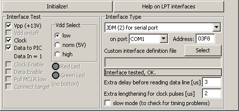
This page regroups the selection, configuration and tests of the programmer interface.
The upper right list allows to select the model of programmer. This choice implies the type of port that is used by the programmer. The second list allows to select the port to use when there are several on the PC. The address field allows to change the physical addres of the port. Though this is generally a critical error to change this value, the effect could be a crash of the PC.
For the cutstom interfaces it is necessary to select a file that describes the programmer behavior. This is done using the Select button. It is also possible to enter directly the filename in the text field. The interface definition file contains the rules that allows to drive the interface.
The other fields below allows to modify the durations in programmer cycles. Usually it is not necessary to modify them. Though they may help to workaround some weak interface.
The checkboxes on the left allow to modify at will the status of the signal on the device. The Data In value indicates the status of the data input from the device. The optional programmer LEDs and button are indicated too when applicable. This should be necessary only for debugging a new programmer. In fact WxPic performs automatically a programmer test at startup. The result of this auto-test is displayed in the rectangle in the middle of the right panel. The Initialize! button at upper left allows to redo this auto-test.
WARNING: To use a parallel port adapter, it is necessary to install and run WxPic in an administrator account. VISTA users will have to register WxPic as a priviledeged program. To do this, right-clic on the shortcut used to run the program and choose properties. In the Compatibility tab check the box at the bottom.
When using a parallel port you will generally get the error WARNING ! Windows fooled around with the LPT port bits !
This error is caused by Windows writting to the LPT port without even verifying that it has been open by an application. This is probably used to detect a plug-and-play peripheral (printer) that would be plugged on the LPT port. The method to de-activate this polling is to modify the registry:
[HKEY_LOCAL_MACHINE\SYSTEM\CurrentControlSet\Services\Parport\Parameters] "DisableWarmPoll"=dword:00000001
This method is not documented by Microsoft. So it is not sure it will always work. Though it has successfully been tested on XP SP2 and VISTA. You can double-click on the file DisablePolling.reg at the root of WxPic intallation directory to perform this change. In case you would need to restore the polling of the port use EnablePollingBack.reg
The Messages Page

This pages displays the status, debugging and error messages. It should be usefull only in case of error to analyze the details. This is also the page that is displayed during Batch programming. The log window must have the focus when pressing Enter to confirm the start programming for the next device of the batch.
The Clear button allows to empty the message window. It is necessary to perform this operation when the window content size become to large.
The Session Management Dialog

This dialog can be invoked by selecting Manage Sessions... in the File Menu.
It will also be displayed at WxPic Startup if more that one session is defined. In this case no session will be Current.
Session Definition
A session defines a WxPic Configuration. Switching session allows to quicly switch from one configuration to another. In addition different sessions can be run concurently by different instances of WxPic. But be aware that these instances will fail to share the same interface port. Therefore the configurations of sessions to be used concurently MUST refer to different interface ports (such as COM1 and LPT1 or COM1 and COM2). Note that it is not recommended to use more instances than you have cores (or threads for multi-threaded cores) in your computer CPU because each instance of WxPic uses a full thread while working with the adapter.
- The parameters of a session configuration are:
-
- The Interface Port,
- The Adapter Definition,
- The Programmed Device Model,
- The Default Hex File,
- The Programming Modes.
- Quit WxPic in standard way (Click on the window close box or Quit menu)
- Switch session using the Session quick selector,
- Click on the Save Configuration Button,
- Confirm the Save proposition made by the Switch to operation of the Session Manager.
- Quit WxPic without saving,
- Drop Change of the configuration.
- A session configuration does not include:
- This means that these parameters are shared between sessions, saved on each modification for the first three, saved on program exit for the next two.
It exists 2 special sessions
- The Current Session
- This is the session currently in use by the current instance of WxPic. Its configuration is loaded in the program. Though while the Session Management dialog is open, the changes made to the configuration are not reflected in the main WxPic Window below. It will be updated when it gets back the focus.
If several instances of WxPic are running concurrently they cannot have both the same Current Session. It exists only one case when the Current session does not exist: this is at WxPic startup if more than one session is defined. In this case the Session Management Dialog is displayed without any Current session. - The Default Session
- This session will always be displayed at the top of the list with the [Default] marker. It will be created automatically the first time you run WxPic. This automatic creation is uses either default parameter values, or when available, parameters recovered from a previous session-less version of WxPic (versions prior V1.3). The Default Session cannot be deleted but its configuration can be edited without restriction.
The session states are:
- Available
- The session is defined but no WxPic instance was using it.
- In use
- The session is not available because it is used by another WxPic instance.
- Current
- The session is used by this instance (the one that displays this state). Only one session is Current in each WxPic instance, this is the Current Session.
In the session list, the state of the session is indicated between parenthesis after the session name. Note that the session state is determined at the moment the list is displayed or when an operation in this WxPic instance modifies the state of the list. But it is not updated when another WxPic instance causes a status change.
Session Manager Operations
- New Session
- Creates a new session that will be added to the list. This session starts with the same configuration as the previous session configuration or with default parameters when there was no current session. The created session becomes the Current session.
No more than 20 sessions can exist at a given time. So New Session button will be disabled if this number of sessions have been reached.
The Operation may fail if another instance of WxPic has already created the 20th session - Switch to
- Set the selected session in the list as the Current session. Loads the configuration of this session. The former Current session is freed and becomes Available. If that session had unsaved parameters, a confirmation is requested, allowing either Saving these changes before switching to the new configuration, Droping these changes or cancelling the Switch to operation. And if the session name had been modified but not saved, a similar dialog will be displayed to allow renaming the session before leaving it.
It is not possible to start using a session already used. So the Switch to button will be disabled if the selected session is not Available.
The Operation may fail if another instance of WxPic has deleted or started using the selected session. - Switch and Close
- Execute successively a Switch to operation followed by a Close operation. Refer to these operation definitions. The Close operation will not be performed if the Switch to operation fails or is cancelled. Note that double left-click on an Available session is a shortcut to invoke this Operation.
- Delete...
- Delete the selected session. A confirmation will be requested because deleted sessions can't be restored.
It is not allowed to delete a session that is In use or Current. Therefore the Delete... button is disabled if the selected session is not Available.
The operation may fail if another instance of WxPic has deleted or started using the selected session. - Refresh list
- Update the content of the Session List. This is only usefull if you have updated the session states from another instance of WxPic. The list is automatically updated upon modification performed in this instance of WxPic or each times an operation fails because of an unexpected change made from another instance.
- Help
- Display this section of the help
- Close
- Close the dialog. If no session is Current at this time WxPic will exit. Else the WxPic operations will resume with the configuration of the Current session. If the session name had been modified but not saved, a confirmation dialog will be displayed allowing either Renaming the session before closing, Droping these changes or cancelling the Close operation.
- Rename
- Apply the changes made to the current session name in the text field above the button. Note that Session name length is limited to 30 characters maximum and that 2 sessions cannot have the same name ignoring the case. The leading and trailing spaces are ignored and series of spaces inside the name are replaced by a single space. In addition quotes should not be used in session names. Else they cannot be specified on command line.
This button is disabled if no change has been made to the session name. - Save Configuration
- Save the configuration of the Current session.
This button is disabled if the session has no modified parameter. - Drop Change
- Discard the changes made to the configuration of the Current session.
This button is disabled if the session has no modified parameter.